The Ultra High Frequency Receiver Hallicrafters S-27 is a very early all wave
receiver covering the VHF range up to frequencies in the 2 m band, this frequency
range was in those days adressed as "ultra high frequency", nowadays we are speaking
of "very high frequency" (VHF).
The set was usually used for band monitoring purposes, even when it was developed
in the forties, this was still many years ahead of the use of the VHF range for
broadcasting purposes. VHF broadcasting started in the USA in the 6 m band
on frequencies around 50 MHz and was later reallocated to the 3 m band up to
100 MHz. Also the aircraft communications were moved to the VHF range from
118 - 137 MHz not before the end of World War II.
The S - 27 is a hollow state receiver covering the VHF range. The set
developed around 1940 covers the 27 - 145 MHz frequency range, the later
S - 27B version covers the 36 - 165 MHz frequency range.
The standard S-27 UHF receiver is powered by 115 Volts AC, the common
mains voltage found in the USA. A part of the receivers shipped to Europe
came with an optional "universal transformer" (model designation S - 27U),
on which, different voltages from 110 - 250 Volts can be selected. So do not
simply fix a plug on your newly acquired S-27 and connect it to the European
230 V mains, but make sure the voltage, your receiver is set to, before powering
up. If there are any doubts, use a variable isolation transformer and increase the
voltage slowly up to 110 V and check, whether your radio is already running
properly, so it will be wired for 110 V operation.
The receiver comes in a rugged metal case with a hinged lid giving you access
to the chassis to exchange the valves, it's dimensions are 48,3 x 23 x 25,6 cm
and it's weight around 20 kg.
On the left side of the front panel, you find the rotating backlit main frequency
dial, in contrast to the metal disc dials on older Hallicrafters models, only a part
of the dial is visible behind the dial window. In the left lower corner of the
frequency dial, you find the three position bandswitch. This lets you select
one of three frequency ranges (27,8 - 47 / 46 - 82 / 82 - 143 MHz).
Just below, you find the R.F. gain
control, the antenna trimmer, a bandwidth control (SHARP - BROAD) which also acts
as mains switch and the A.F. gain / volume control at the right.
At the right of the main tuning dial, you find the fine tuning dial, which is
mechanically coupled to the main tuning and is operated with the the typical Hallicrafters
"steering wheel" tuning knob, below you find the switches for ANL (which activates automatic noise limiter),
the AM / FM mode control, below the BFO switch and at the right the BFO pitch control
used for single sideband and CW reception.
At the right, below the signal strength meter, you find the tone control and at the
right the Send / Receive switch (to mute the receiver when used in connection
to a transmitter) and the headphones jack. A high impedance speaker (5000 Ohms)
can be connected at connectors at the rear of the receiver, to drive an 8 Ohms speaker,
you need a matching transformer.
When You have managed to apply the correct power to the receiver, it's operation
scheme is different in AM and in FM mode.
Use the selectivity control to turn the radio on (yes - that's typical Hallicrafters, not
to combine the mains switch with the volume control), turn the R.F. gain to the maximum setting
clockwise and the A.F. gain somewhere in a middle position and select the frequency band.
The AVC should be activated (switch to the left) and the BFO should be
turned off, make sure, the SEND/RECEIVE switch is in the RECeive position.
In AM mode, You can try to catch some morse code transmissions or communications in the 10 m ham band above 27 MHz
with the BFO turned on, sometimes, You get better results in copying CW or single
sideband signals with manual R.F. gain control. There is also some AM communications activity
in the Air band in the 118 - 137 MHZ, e.g. airport weather reports around 127 MHz.
In the FM mode, look for some FM broadcast stations in the standard FM broadcast band
from 88 - 108 MHz, BFO, AVC and ANL is inactive in this mode, the selectivity has to be set to BROAD
for broadcasting stations, and the TONE control can be set to HIGH FIDelity or even
BASS BOOST. The reception uses a deemphasis constant of 100 usec., the meter is
switched to act as a tuning indicator with optimal tuning when the indicator is in
the middle position. In some cases, the antenna has to be tuned to maximum signal strength.
Besides FM broadcast transmissions, you can hear some amateur radio communications in
the 2 m band around 144 MHz and maybe some test transmissions of vintage military
gear in the military FM band between 30 and 76 MHz; there is some amateur radio
activity around 50 MHz in the 6 m band. Television does not use VHF band I anymore
in Europe.
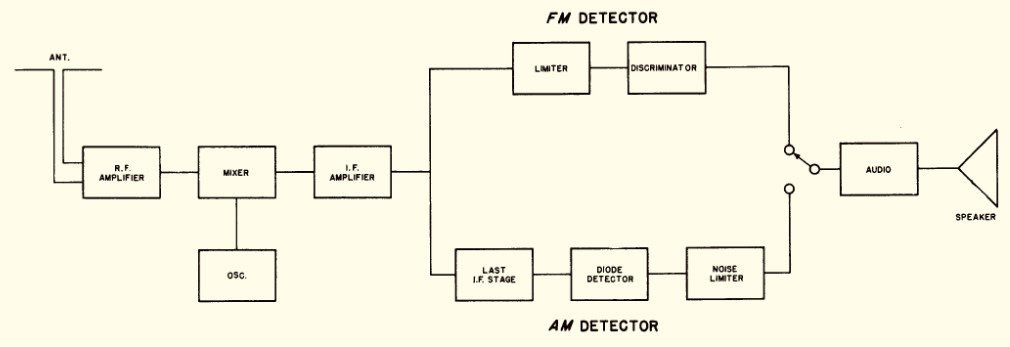
Signal path: The signal coming from the antenna is amplified in a RF amplifier stage using
a acorn miniature tube (V1, acorn tube 956) and is fed to the mixer stage
(V2, acorn tube 954), where the oscillator signal (V3, acorn tube 955) is used
to generate a 5,15 MHz intermediate frequency. After a first IF amplifier stage (V4, 6AC7/1852),
in AM mode, the signal is fed to a second / third IF amplifier stage (V6, 6AB7/1853
and V7, 6SK7) and a diode for AM demodulation (V8, 6H6). For FM operation,
the signal has to pass a limiter stage (V9, 6AC7/1852) and is fed to the discriminator
stage (V10, 6H6) for demodulation.
An 6C8 is used in as AF preamplifier and two 6V6 in a push pull arrangement in
the AF output stage. For the BFO, a 6J5 valve is used.
In the power supply, a 5Z3 valve is used as full wave rectifier and
a VR-150/0D3 voltage regulator.
The S-27 is a very early example of a VHF wide band receiver, it has been used
as a surveillance receiver by the Swiss Armed Forces.
On a historic photograph of the VHF monitoring post in the Sphiny observatory
on the Jungfraujoch, a E-624 / Hallicrafters S-27 receiver used as VHF surveillance
receiver can be identified.