|
|
Shortwave Receiver E-629 / Collins 51J-4
|
|
|
überarbeitet am 1.9.2010 |
After WWII, Collins presented their first all wave receiver covering all frequencies from mediumwaves
to 30,5 kHz shortwaves, the 51J - a short time later the 51J-1 appeared in 1949
and was built in small production numbers only. After major technical improvements,
the 51J-3 has been built in larger quantities, it's military tropicalised
version carried the R-388 designation. Only the later 51J-4 was equipped
with Collins' famous mechanical IF filters - the U.S. military designation of these
sets with the mechanical filters installed was R-388A.
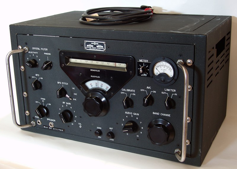
The Collins 51 J-4 is a typical "boatanchor" equipped with a total of 19 valves, it's dimensions with the cabinet included are 53,6 x 31,7 x 33,3 cm, quite frequently it has been sold as 19" rack version. It's weight is 21,3 kg, the set can be powered by 115 or 230V AC and has a power consumption of 85 Watts. The 51J-4 has no internal speaker, at 4 Ohm speaker or a 600 Ohms high impedance spaker can be connected to the speaker connectors at the rear of the set. In the centre of the front panel, You find the linear analog drum dial
displaying the selected 1 MHz segment with 100 kHz marks. Underneath bext to
the main tuning knob You find a window displaying a segment of a circular dial
calibrated in 10 kHz marks, between the 1 kHz-lines You can read a tuned frequency
with an accuracy of around 500 Hz. In the lower row of controls You find from the left to the right the mains
switch, in the "Standby" - position all the valves heaters are on
and the receiver will work immediately when switched ON, then at the left of the
main tuning knob the RF (radio frequency) gain and at the right side the volume /
AF (aufio frequency) gain control. A second big rotary control will act as bandswitch,
moves the dial drum controlles the preselection over several mechanical gears.
Two small controls in the middle underneath the main tuning knob will operate
the moving calibration line in the kHz-dial window and the antenna tuner.
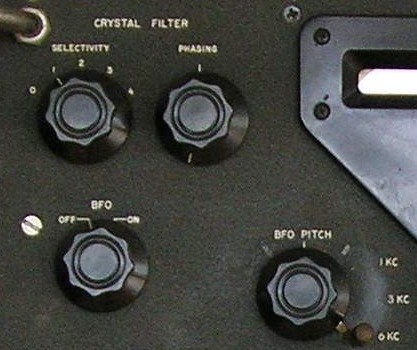
The HF circuit of the 51J-4 is nearly as complicated as the mechanical synchronisation of the preselection using very impressive gears. In the 0,5-1,5 segment, the 51J-4 uses triple conversion, the signal will be converted to 11,5-10,5 MHz in the first mixer and to the usual 3,5-2,5 MHz in the second mixer. In the 1,5-3,5 segments, the receiver is switched as single conversion and the signal directly proceeds to the second mixer. In the other shortwave bands from 3,5-30,5 MHz, the typical double conversion circuit takes action: In the shortwave bands with even MHz counts, the signal is mixed to 1,5-2,5 MHz after having passed the first RF amplification stage, in the bands with uneven MHz counts to 2,5-3,5 MHz. In the second mixer, the signal is converted to the second intermediate frequency of 500 kHz. The signals first has to get passed the switchable crystal filter and the through the bank of mechanical IF filters. After another RF amplification stage, the signal is passed over to the detection stage and into the AF stage. Most sets used by the Swiss Army have been modified with a S-meter zero knob next to the signal strength meter, so You can recognize them easily.
further reading: © Martin Boesch |
||||||||||||||||||||||||||||||||