|
|
Shortwave Receiver E-645 / Siemens E311
|
|
|
überarbeitet am 1.9.2010 |
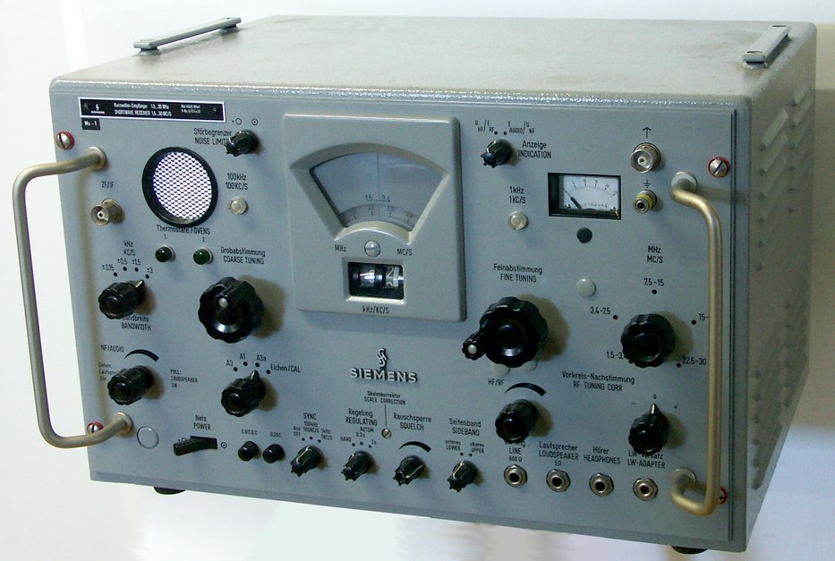
The Siemens E-311 appeared in early 1960's in parallel to the E-310 and was advertised as an alternative to communications receivers from Collins or Rohde & Schwarz. It has not only been in use in Germany but has also been used by the Swiss Army, where it carried the designation E-645.
With it's grey steel cabinet with the dimensions 47,5 x 29,5 x 39 cm and a weight of only 25 kg, the Siemens E-311 is a quite compact and lightweight commercial communications receiver. All connectors can be found on the front panel, even the mains cable for the 110 - 220 V mains supply. The 16 valves in the receiver have a power consumption of 70 W, the quartz ofen needs another 30 Watts. According to the setting of the band switch, another segment of the frequency dial is visible in the dial window, on the dial, You find the coarse 100 kHz marks. A mechanical digital (odometer type) display will indicate the frequency with a resolution of 1 kHz, there are incremental lines for 100 Hz. With the coarse tuning knob at the left hand below the frequency dial, You select the next lower 100 kHz frequency mark on the band dial, a indicator lamp just above the dial will inform You that the receiver is locked on the the correct 100 kHz position, then use the fine tuning knob at the right lower hand to select the 10 kHz and 1 kHz digits of the desired frequency. The speaker grille of the internal monitor speaker is found in the left upper
corner of the frontpanel, the speaker is activated when the volume control is
pulled. At the right, You find the switch for the noise limiter, the 100 kHz
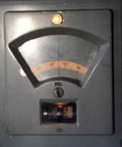
lock indicator and below the indicators for the quartz ofen and oscillator
temperature. Below, You find the bandwidth control, and further below the rotary volume control
and the modes switch for AM(A3), CW(A1), SSB(A3a) and "Calibrate" just next to it. The RF signal coming from the antenna jack has to pass the preselector stage,
an amplifier and filter stage and will be coverted to the first intermediate frequency of
1,3 - 1,4 MHz. In the second mixer, an I.F. of 370 kHz is generated and mixed with
an oscillator signal of 400 resp. 340 kHz to end wit hthe third intermediate
frequency of 30 kHz. After having passed a 30 - 33,5 kHz band filter, the
signal can be decoded for single sideband reception or will have to pass
a detector diode in AM mode. A beat frequency oscillator of 31 MHz is used
for CW reception.
The small range of the fine tuning oscillator makes tuning through a
complete shortwaveband a bit cumbersome - when You cross the 6099 - 6101 kHz
point, You have to set the main tuning knob to the next 100 kHz segment
and turn down the fine tuning knob of the interpolator from 99 to 01. For these
situations, You can switch off the 100 kHz locking circuitry and use only the
coarse tuning knob to search for a certain signal. weitere Lektüre: © Martin Bösch |
||||||