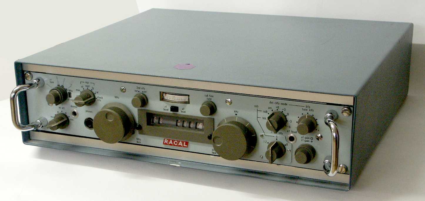
The Racal RA-17L, the first shortwave receiver based on the famous Wadley Loop design
developed by Dr. T. Wadley, has been in service at the Royal Navy for years.
The RA-1217 was the solid state successor of this famous set with an "odometer
type" mechanical frequency display.
The compact receiver in it's metal cabinet is with 48,3 x 8,9 cm quite unique in
it's dimension, it's weight is 11,3 kg. The Swiss Army variant E-655 came in a
wooden transport case, together with the complete manual, cables and accessories,
You end up with 44 kg.
The K + W Thun works prepared a simple user's guide printed on an aluminum plate,
this makes it easy to find the correct settings for standard use.
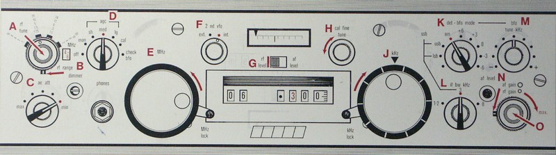
Use switch D not only to turn on the receiver, but also to select the AGC speed - the position
“AGC med” as shown works well to get started.
To avoid bad results due to misuse of the controls, select the internal VFO (switch F),
the attenuator (switch C) should be set to minimum, the R.F. gain (control O) to maximum
and the A.F. gain control (control N) should be set to a slight hiss to be audible in the
headphones.
Use the left tuning knob (E) to select the MHz digits of the desired frequency and
the right 0 - 999 tuning knob (J) to select the other digits of the desired frequency.
As found in other receivers based on the Wadley Loop design, the correct use of the
preselector is very important for good results. Select the correct frequency range
and tweak to maximum signal in the headphones and the signal strength meter.
For reception of a standard Am signal of an international shortwave broadcaster,
the modes switch (switch K) should be in the "am" position.
Use the modes switch to set the receiver to single sideband reception (usb or lsb),
with the second "if bw" (L) switch, You can select a narrow SSB bandwidth of 3 or 1,2 kHz.
For CW reception of morse code transmissions, use the "det bfo" position of mode switch K
and the BFO beat note control M. In special reception conditions, You can very the AGC speed
with switch D, to just scan a band, sh(ort) is recommended, for SSB / CW reception, l(ong) might
be Your choice.
The signal path of this receiver based on the “Drift cancelling system” respectively
the “Wadley Loop” circuitry ,developed by Dr. T. Wadley for Racal, is a bit complex:
In contrast to standard superhets, the receiver comes without a standard bandswitch: the
MHz tuning knob selects one MHz segment of the shortwave spectrum, the kHz tuning
knob extracts the desired frequency out of the segment 1 MHz wide.
The circuitry is based on two loops controlled by the first VFO, the MHz tuning system.
One loop is the “Signal Loop”, the other one the “Harmonic Mixer Loop”. In the “Signal Loop”,
the output of the first VFO is mixed with the R.F. signal with the result of a spectrum with
a bandwidth of around 1 MHz. In the “Harmonic Mixer Loop”, the second portion of the output
of the first VFO is mixed with the harmonics of a 1 MHz reference quartz oscillator.
Both mixed products are subtracted in the second mixer stage, a frequency drift of the main VFO
will be substracted in the two parallel signal precessing paths and will disappear,
that's why the output signal from the second mixer is very stable, a special high
stability reference quartz oscillator can be used to further improve stability.
In the case of the Racal RA-1217, the radio frequency signal has to pass the preselector and
is mixed with the output of the first VFO (running from 41,5 MHz (1 MHz range) to 69,5 MHz (29 MHz range)
in the "signal loop" to result in an intermediate frequency of 40 +/- 0,65 MHz, only this
signal will pass a 40 MHz bandpass filter.
In the “Harmonic Mixer Loop”, the output of the first VFO will be mixed with the harmonics of
a 1 MHz quartz oscillator, all exact multiples of 1 MHz, in the "Harmonic Mixer" and the product will
have to pass a narrow 37,5 MHz bandpass filter.
In the second mixer, the output from the “Signal Loop”, the signal in the 40 MHz range representing
one Megahertz of the shortwave spectrum, is mixed with the 37,5 MHz signal from the “Harmonic Mixer Loop”
- subjected to the same VFO drift -
to result in an intermediate frequency of 2 - 3 MHz (exactly 1 MHz wide).
This signal is mixed with the signal of the second VFO used for kHz tuning: From the 2 - 3 MHz
spectrum and the linear VFO signal from 3,6 - 4,6 MHz, the result is a third intermediate frequency
of 1,6 MHz. After four amplifier stages and after having passed the bank of quartz i.f. filter,
the signal is demodulated in a diode for AM signals and handed over to a product detector for
SSB mode signals. For LSB and USB modes, the set has a fixed frequency BFO, for CW reception,
the BFO's frequency can be tuned with the BFO note control.
The standard RA-1217 has an output power of only 10 mV, just enough to drive some headphones.
For reception of the VLF band below 0,98 MHz, a converter is used to shift the frequency in
the 2 - 3 MHz I.F. range. There has been an optional panoramic display to visualize the R.F.
signals in a certain band segment.