As a replacement of the C-3606, the Morane D-3800 (72 pcs.) and D-3801 (289 pcs.)
aircraft, several jet fighter aircrafts have been evaluated after the end of World War II.
After four DH-100 Mk1 had been obtained for evaluation and tests, after 1948 175 aircraft DH-100 Mk6
"Vampire" have been ordered, they stayed in service until their final withdrawal in the year 1990,
which makes a time span of more then fourty years.
Of the improved model DH-112 Mk1 / Mk 4 "Venom" another 126 + 100 aircraft have
been produced unter licence in Switzerland from 1954 on.
In both aircraft of British origin, the crystal controlled VHF aircraft radio STR. 9
made by the British Standard Telephones and Cables (STC) was installed. The earliest
version STR.9 came with only four crystal controlled channels (SE-012 / FG XII),
in the later DH-100 Mk.6 "Vampire" and DH-112 "Venom" aircraft, the improved ten channel
variant STR.9-X / SE-015 was installed.
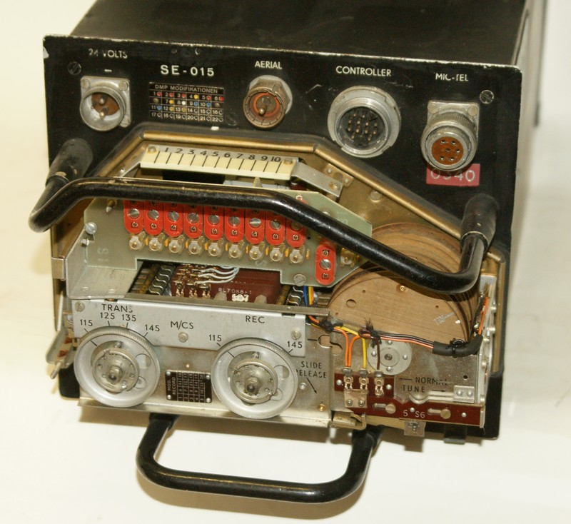
The hollow state VHF aircraft radio SE-015 / STR.9-X, used in the fighter
aircraft de Havilland "Vampire" und "Venom", is completely crystal controlled.
A simple Control Unit is used to select one of ten pre-tuned operation frequency
channels, the "Push-to-Talk" switch is also located at the control unit.
The aircraft radio has the characteristic modular construction: there is
only space for a small control box in the cockpit of most fighter airplanes,
the transceiver itself is located in an equipment bay usually located at the
back of the aircraft. Several cables with multi-pole connectors (which are
typically unavailable when searched for years later) connect the radio equipment
with the on-board instalations of the plane.
After taking away the front cover, the crystal sockets can be accessed, they
are suited to fit frequency crystals of the STC types 4004, 4044 and 4046
or the american equivalent HC/6U, the correct crystal frequency is (operation
frequency divided by 18 - 0,54 MHz).
To tune the set, the transceiver has to be turned on with the control unit attached.
The set has ten frequency channel slide strips for the ten pretuneable channels.
After the slide releasing switch has been pulled outwards. For tuning the receiver
section, the slide switch has to be pulled out for the first stop and the
receiver tuning control is turned for maximum noise after the tuning control
knurled locking disk is loosened. The the slide switch has to be pulled out
for the maximum position to tune the transceiver section for maximum signal
output, then the slide switch has to be set back in the middle position and
the procedure is repeated for the next channel slide strip. After all pre-tuning
is done, the knurled locking disks can be tightened and the channel strips
are then moved electrically when the channel selector at the control unit
is operated.
The transceiver is powered from the 26 V on-board power system of the
aircraft, the heaters are powered directly, a rotary transformer is used to
generate the plate voltage of 250 V and the grid voltage of 50 Volts.
A crystal controlled oscillator gives a signal between 5'848 - 7'515 kHz
depending on the crystal in use, the operation frequency is generated by means
of a frequency multiplier (two frequency tripler stages 3V1 and 3V2 and a
frequency doubler stage 3V3). The operation frequency is the 18-fold of the
crytsal frequency plus 9,72 MHz of the intermediate frequency.
I nthe receiver section, the antenna signal is moxed to generate an intermediate
frequency of 9,72 MHz. This will have to pass three IF amplifier stages to be
demodulated in a diode demodulator.
In transmit mode, the same oscillator signal after the first two frequency tripler
stages is used, it will be mixed with a 4,86 MHz oscillator signal and will be
fed to the modulator stages 4V2 / 4V3. After a frequency doubler stage 4V4
it is passed over to a RF dirver and final amplifier stage 4V5 and 4V6. The
frequency of the emitted signal equals the 18 fold crystal frequency plus the
double auxiliary oscillator frequency.
One example: with the 6,96 MHz channel crystal frequency, an oscillatorsignal
of 62,64 MHz is generated after both frequency tripler stages 3V1 / 3V2,
after beeing mixed with the auxiliary oscillator frequency of 4,86 MHz, a signal
of 67,5 MHz is fed to the last frequency doubler stage 4V4, from which the
final output on 135 MHz in the middle of the VHF air communications band will
will result, this only needs further amplification to be transmitted.
The first four aircraft of the early DH-100 Mk 1 had the four channel STR 9 / SE-012
installed, the later DH-100 Mk 6 "Vampire" and DH-112 "Venom" came with the ten channel
version STR.9X / SE-015. Later, the major part of the Swiss Air Force fleet has
been equipped with this equipment, e.g. the C-3605, Pilatus P2, P3, PC-6, Do-27, Ju-52, Fieseler
Storch and even the Hawker "Hunter". There also exists a 44 channel variant, the
SE-015/1.
I would be very thankful for further information and images.