|
überarbeitet am 21.4.2012
|
The venerable Collins 51S-1, a very compact allwave receiver with a mixed mechanical analog frequency dial, has also been in use with the Swiss Army, probably in the signals intelligence section.
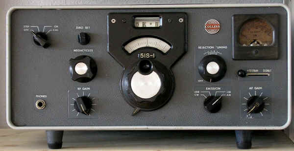 |
triple conversion, I.F. 14,5-15,5 MHz, 3-2 MHz, 500 kHz
linear Analog dial 1 kHz
AM, USB/LSB, CW
|
Sensitivity 5 MHz
AM <3 uV, SSB < 0,6 uV
Selectivity -6 dB
0,8 / 2,4 / 5 kHz
RF-Gain, Attenuator, Crystal Filter
|
The Collins 51S-1 with it's metal cabinet painted in grey is a very compact set compared to the E-629 / 51J-4 receiver; its dimensions are 37,5 x 16,7 x 33,2 cm and its weight 11,8 kg, - a hollow state double conversion set in such a small cabinet is a suprising bit of engineering.
The 51S-1 is prepared to be powered by 115 or 230V AC, the power consumption of the 17 valves is 125W.
The different rear connectorsmake it obvious, that the 51S-1 has its roots among the professional receivers: there are not only connectors for low and high impedance antennas but also for an external VFO, a 500 kHz IF output, and a connector for a long- and mediumwave converter.
The front panel gives a very basic first impression: in contrast to several older professional receivers from Collins, the 51S-1 comes with only nine frontpanel controls: The analog dial has an accuracy of better then 1 kHz, the MHz-digit is moved by the MHz-bandswitch and the 0.1 MHz digit is moved by the main tuning knob like an odometer, You hear a click when You go passed a ...99 / ...101 kHz step. You can adjust the zero line of the main dial with the "Zero set"-knob using the internal crystal calibrator signals or the signal of a frequency standard or time signal after having tuned to zero beat.
The mains switch in the left upper corner has a "Standby" setting (in this setting, the valves are heated and frequency stability is reached immediately after switching the set to "On", there is also a position to activate the crystal calibrator.
The RF gain and AF gain / Volume controles are situated at the left and the right of the main tuning knob. Between this and the AF gain control, you find the modes switch - upper and lower sideband filters can be switched independently - and a control called "Rejection Tune" slightly above. This activates the Crystal Filter used to notch out unwanted signals.
The I.F. bandwidth filters switching is coupled with reception modes: in AM reception a LC or optional a much more expensive 6 kHz mechanical filter is in use, for USB/LSB a 2,4 kHz or an optional 2,75 kHz mechanical filter is switched in the circuit, for CW reception a 800 Hz crystal filter or an optional narrow 200 Hz filter.
The S-meter in the right upper corner of the front panel can be switched to display the RF or the audio frequency level.
The high frequency signal from the antenna input will first pass a bandpass filter and the mechanically coupled automatic preselection stage. In the 0,2 - 2 MHz ranges, the signal is internally up-converted to 28-30 MHz.
In the 2 - 7 MHz band segments, the signal will - after the first RF amplification stage - be converted to 14,5-15,5 MHz, in the second mixer to 2 - 3 MHz and in the third mixer to the last IF of 500 kHz - thus triple conversion operation.
In the 7 - 30 MHz segments, the signal will be directly converted into 2 - 3 MHz in the first mixer and to 500 kHz IF in the second mixer stage double conversion operation in these ranges.
The 500 kHz IF will have to pass the 6 kHz LC filter in AM mode, the mechanical 2,4 kHZ uSB or LSB filter in SSB mode or the 800 kHz crystal filter in CW mode. After the Q-multiplier circuit with HF notch and two more RF amplification stages, the signal is sent for demodulation to a diode demodulator in AM and a product detector in SSB modes. Two more stages are used for AF amplification.
To me, it's still unclear in which roles the 51-S1 has been used by Swiss Army branches, but the receiver exists in the inventary of receiving equipment.
© Martin Boesch 21.4.2012
|